
ㅤ
TECHNICAL OVERVIEW
KEY PRODUCT
SPECIFICATIONS
POST HEIGHT
38.563 in
POST WEIGHT
13 lb
BASE DIAMETER
7.677 in (nominal 7.5")
FLOOR PLATE DIAMETER
7.48 in
MOUNTING
Adhesive-mounted ferritic stainless-steel floor plate
EMERGENCY FEATURE
Emergency breakaway belt end supplied standard
PRODUCT GRAPHICS
MAGNETIC-BASE
SYSTEM REFERENCE
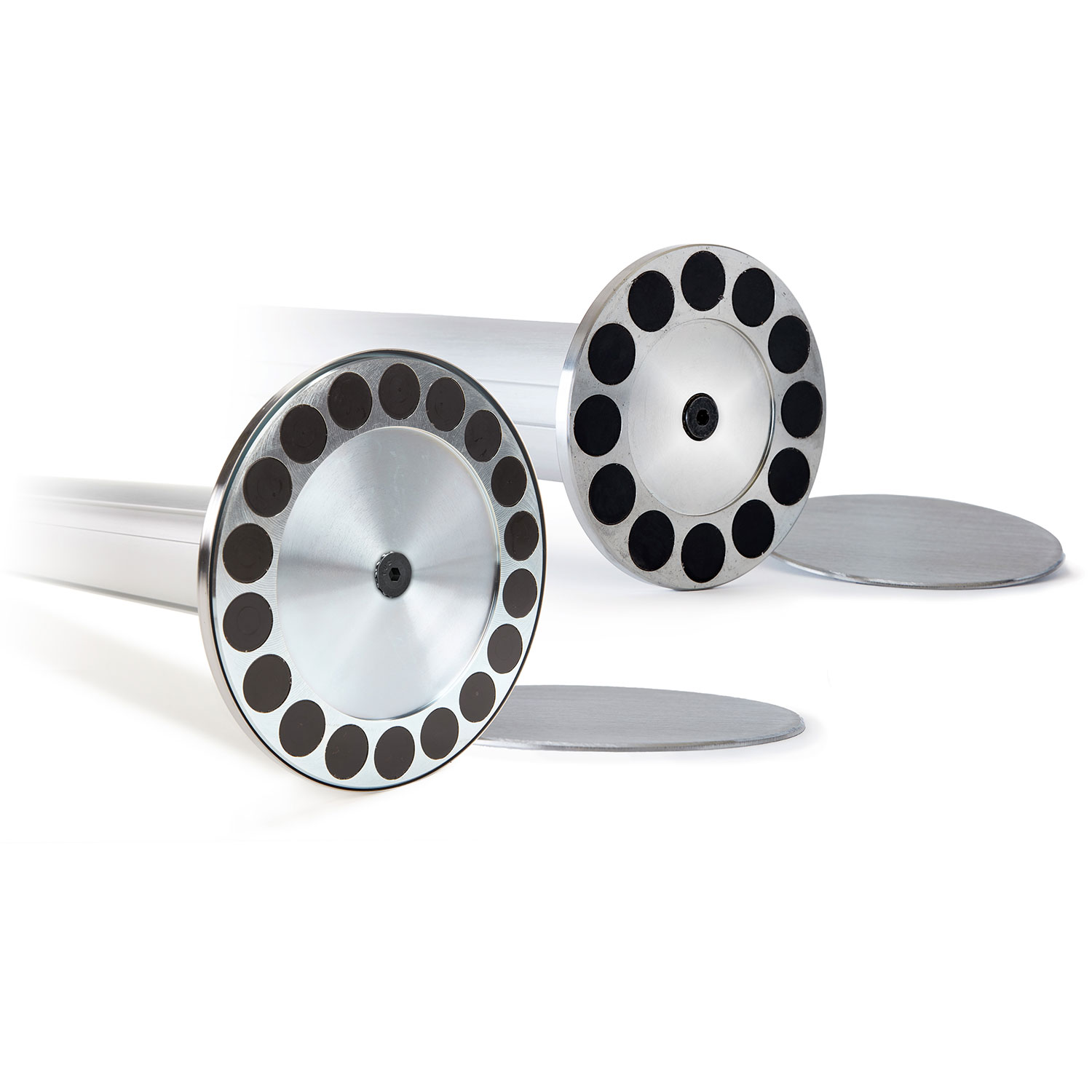
Magnetic-base footprint and floor-plate concept
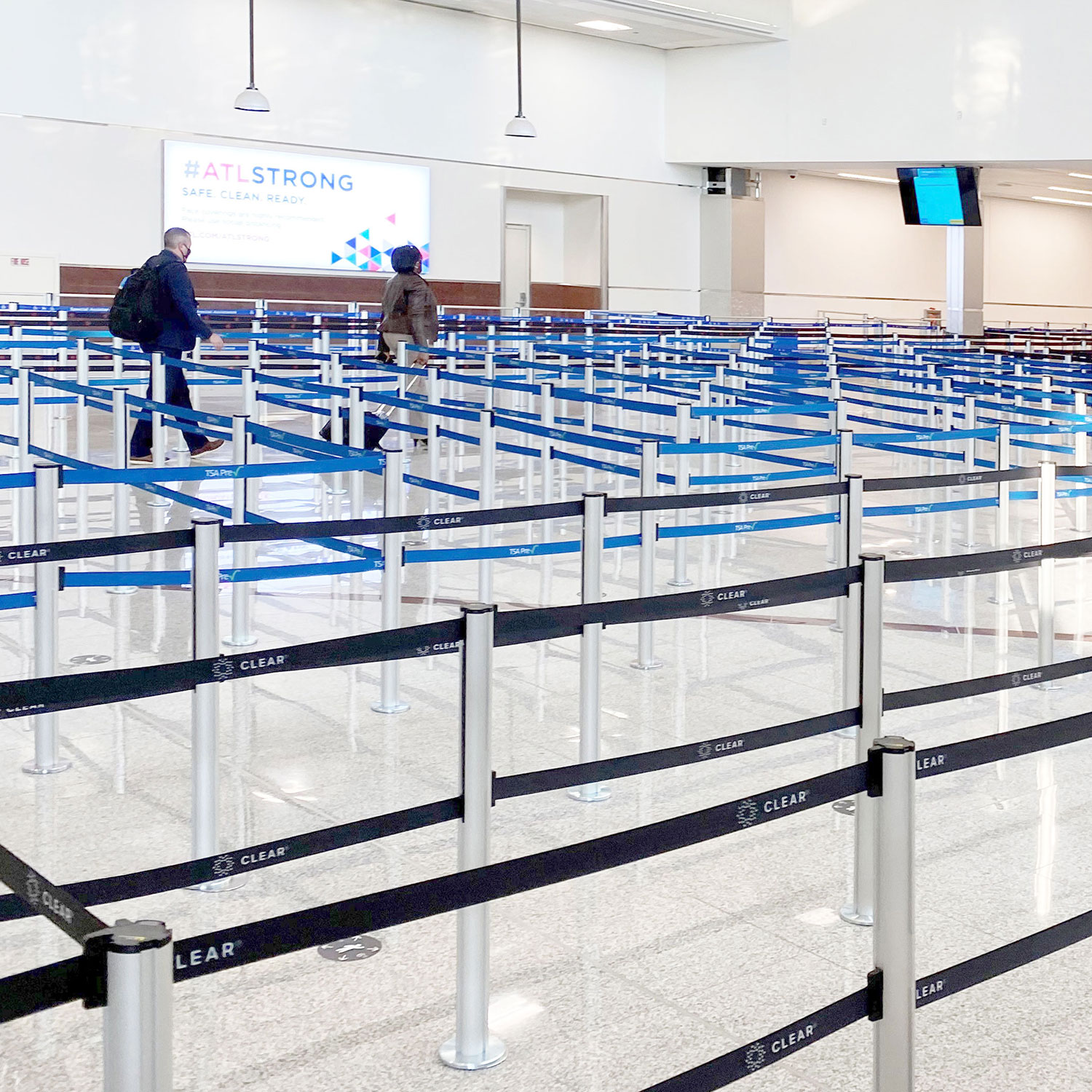
Magnetic-base queue application
INSTALLATION / ASSEMBLY
FLOOR-PLATE
INSTALLATION PROCEDURE
The magnetic stanchion attaches to a permanently positioned stainless-steel floor plate. Correct floor preparation and adhesive curing are important for reliable installation.
01
Assess & Prepare
Confirm that the floor is flat, smooth, even, and free of abrasions. Sweep and clean the surface and allow it to dry completely.
02
Lay Out the Queue
Use layout lines and measurements to mark the intended center points of the stanchions before any floor plate is bonded.
03
Clean the Plate Location
Center the floor-plate template over the marked position and clean the exposed mounting area with rubbing alcohol until residue, oil, and layout chalk are removed.
04
Bond the Floor Plate
Warm the prepared area to approximately 100°F. Remove the adhesive backing, carefully place the stainless-steel plate, and press it firmly into full contact. The industrial adhesive cannot be repositioned after placement.
05
Allow Full Cure
Apply firm pressure across the plate and allow at least 24 hours before attaching a post. A 24–72 hour curing period provides the strongest adhesive bond.
06
Attach the Stanchion
After the adhesive has cured, orient the belt in the required direction, bring the edge of the magnetic base to the floor plate, and carefully rock the base into contact rather than allowing the magnets to slam onto the plate.
INSTALLATION NOTE
The floor plate is intended for installation on an appropriate smooth, non-porous floor surface. Always evaluate the flooring material and installation location before applying the adhesive plate.
TECHNICAL DOCUMENTS
INSTALLATION & SERVICE
RESOURCES
|
PRODUCT GRAPHIC |
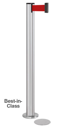 15 FT
15 FT
|
10 FT
|
15 FT
|
10 FT
|
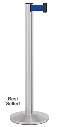 15 FT
15 FT
|
10 FT
|
10 OR 15 FT
|
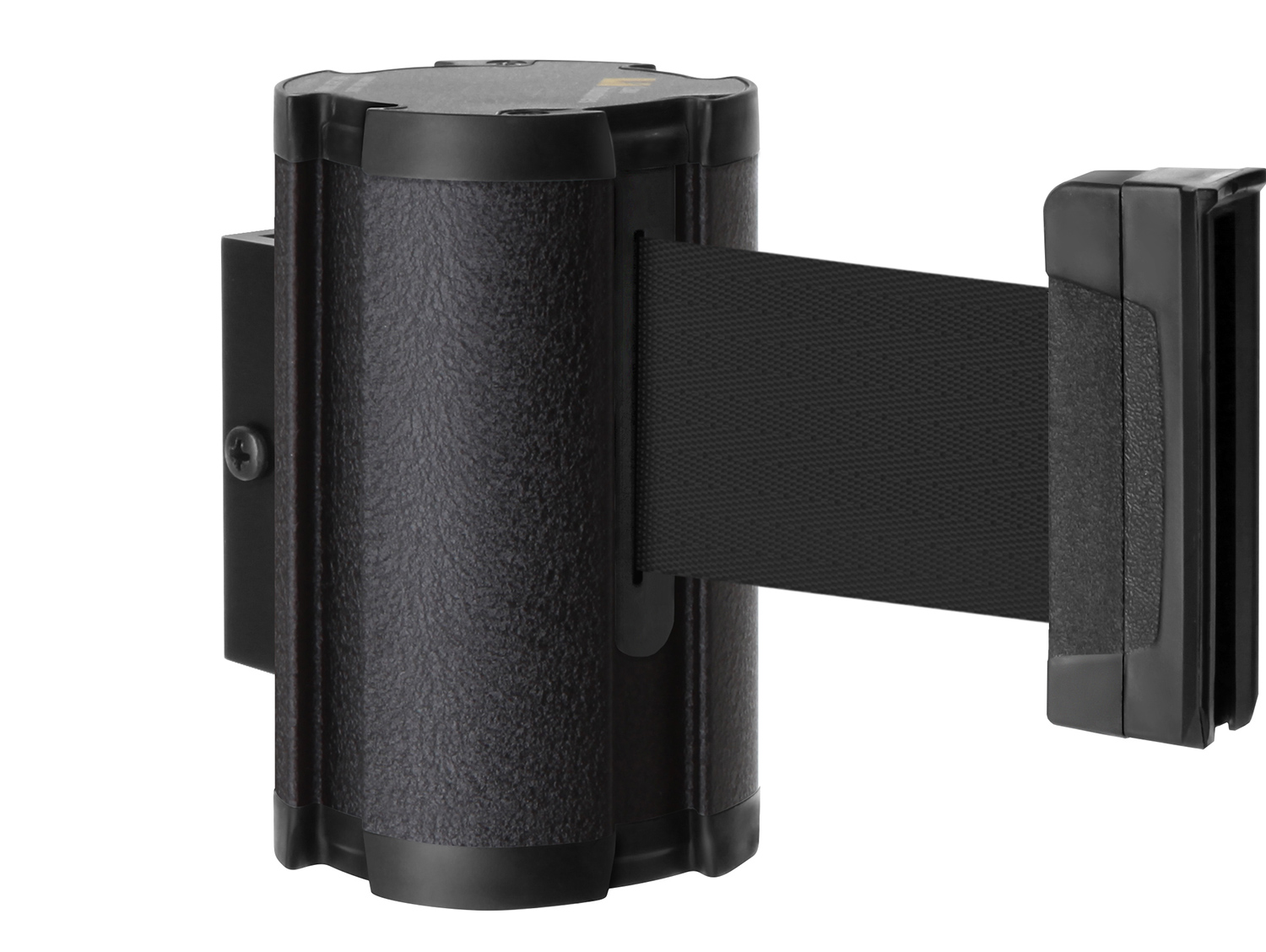 10 OR 15 FT
|
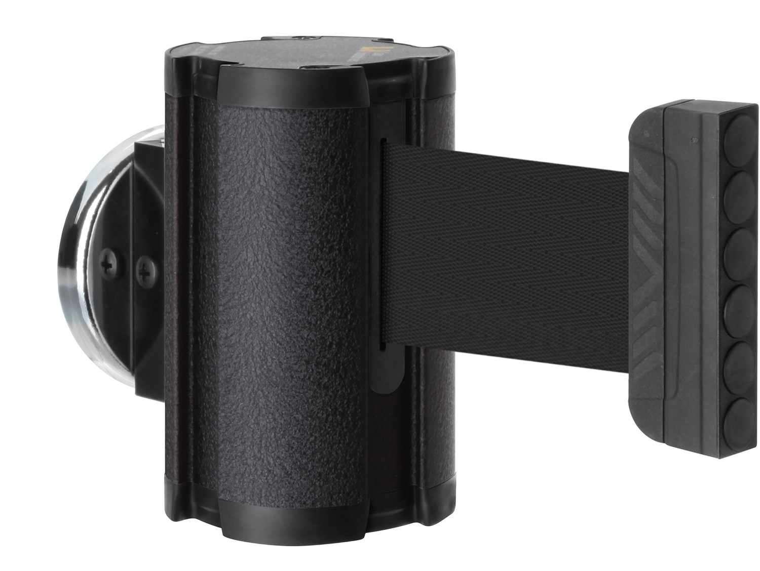 10 OR 15 FT
|
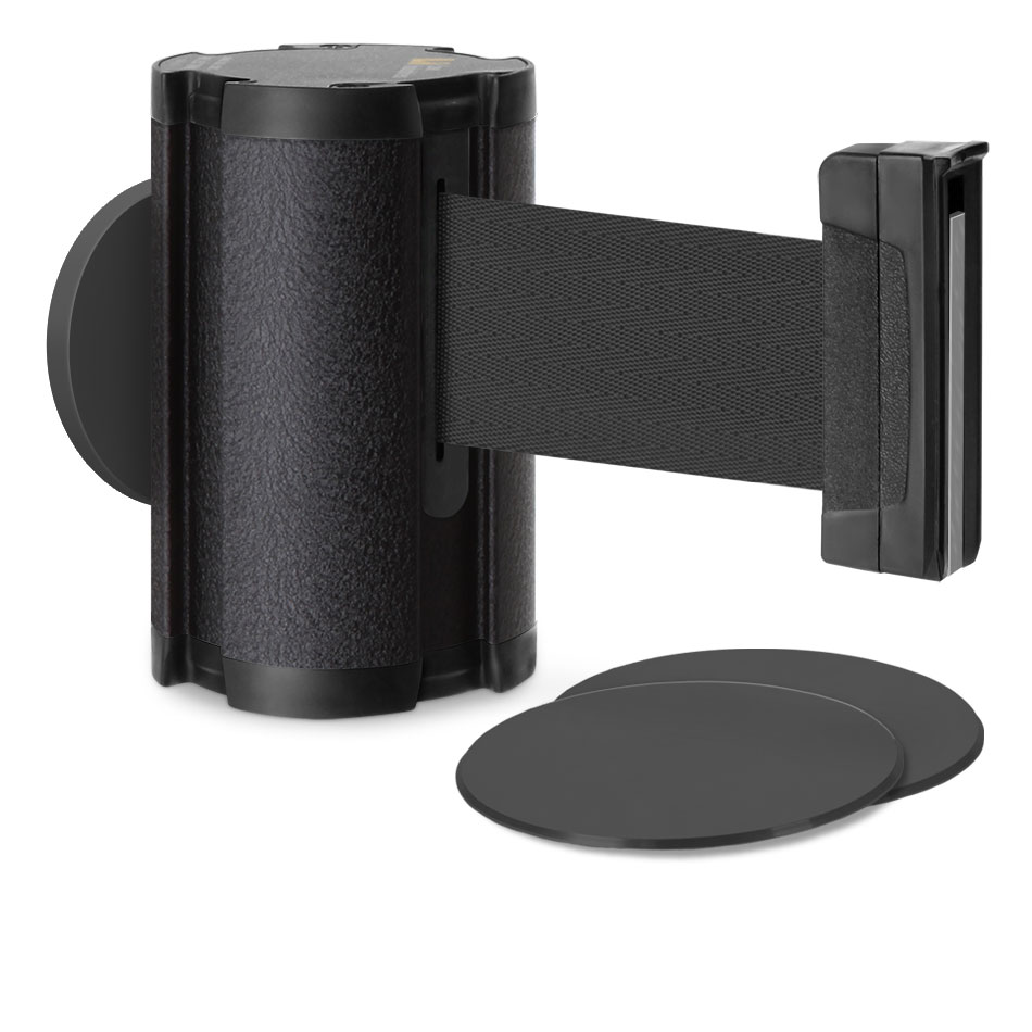 10 OR 15 FT
|
|---|---|---|---|---|---|---|---|---|---|---|
| PRODUCT |
7.5" Heavy Duty Magnetic Base - 15 Feet
CURRENT PRODUCT
|
7.5" Heavy Duty Magnetic Base - 10 Feet | 5.5" Magnetic Base - 15 Feet | 5.5" Magnetic Base - 10 Feet | 14" Sloped Base - 15 Feet | 14" Sloped Base - 10 Feet | 14.5" Slim Base | Wall-Mounted Retractable Belt Barrier | Magnetic Wall-Mounted Retractable Belt | Glass/Surface Mount Retractable Belt |
| MOUNT / BASE | 7.5" heavy-duty magnetic floor base | 7.5" heavy-duty magnetic floor base | 5.5" compact magnetic floor base | 5.5" compact magnetic floor base | 14" portable sloped weighted base | 14" portable sloped weighted base | 14.5" portable slim weighted base | Mechanical wall grip connector | Magnetic vertical-surface mount | Adhesive steel plates on glass / smooth surface |
| BELT REACH | 15 ft | 10 ft | 15 ft | 10 ft | 15 ft | 10 ft | 10 or 15 ft | 10 or 15 ft | 10 or 15 ft | 10 or 15 ft |
| BEST WHEN | Long, fixed-geometry queues need maximum magnetic hold | Tighter fixed-geometry queues need maximum magnetic hold | Floor footprint must stay minimal across longer spans | Floor footprint must stay minimal in dense layouts | Portable layouts need wider spans | Portable layouts need tighter turns and spacing | A portable post with a slimmer base profile is preferred | A closure repeats in the same location | A closure must move between steel surfaces | A barrier is required on glass or another smooth surface |
| PRIMARY BENEFIT | 18 magnets + 28.7 lbf tip-over force; removable post | Heavy magnetic hold + controlled 10-ft geometry | Small magnetic footprint with 15-ft reach | Small magnetic footprint for dense queue layouts | No floor installation; fewer posts over wider spans | Maximum portability for compact layouts | Portable stability with 10/15-ft flexibility | Zero floor footprint; opposing receiver included | Tool-free relocation; no permanent fasteners | Creates magnetic barrier points on glass and smooth surfaces |
Tip: on smaller screens, swipe horizontally to compare all configurations.